FLexible PCBs
Premium Flex PCBs at Competitive Prices
- Material Options: Choose from Polyimide, PET, or FR4 (Semi-flex) for your specific needs.
- Versatile Stiffeners: FR4, Polyimide, Metal, and PSA stiffeners available for added support.
- Advanced EMI Shielding: Silver ink/film options for effective EMI protection.
- Layer Flexibility: Offering 1-12 layers for Flex PCBs and 2-40 layers for Rigid-Flex designs.
- Precision Technology: Featuring Blind & Buried Vias and HDI capabilities.
- Certified Quality: ISO9001:2015 Certified & UL Listed for guaranteed reliability and performance.
The Types of Flexible Printed Circuit Boards
Flexible Printed Circuit Boards (Flex PCBs) come in various types, classified based on different criteria. Here’s a closer look at the common classifications:
1. By Layer Count:
Single-Sided Flex PCBs: These have a single conductive layer, ideal for simple applications where minimal circuitry is required.
Double-Sided Flex PCBs: Featuring two conductive layers, these boards allow for more complex circuits while maintaining flexibility.
Multi-Layer Flex PCBs: These have multiple conductive layers, enabling highly complex designs that require advanced functionality within a compact, flexible form.
2. By Design Perspective:
Static Flex PCBs: Designed for applications where the PCB remains in a fixed position, these boards are ideal for installations where movement is minimal or non-existent.
Dynamic Flex PCBs: Engineered for applications where the PCB will be subjected to continuous movement, bending, or flexing. These are perfect for devices with moving parts or those that require frequent flexing during operation.
Request Your Free Quote Today!
Understanding Flex PCBs
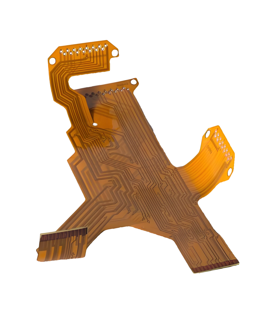
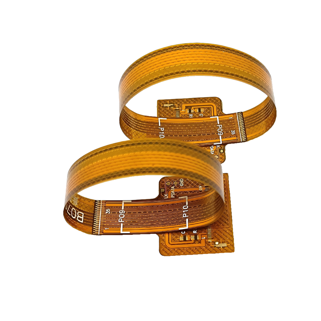
A Flexible Printed Circuit Board, also known as a flex PCB or soft board, is a type of circuit board made from flexible insulating material, allowing it to bend, twist, and rotate freely. This flexibility is its most defining characteristic, making it ideal for a wide range of applications.
Key Materials Used in Flex PCBs:
Flex PCBs are typically made using two main types of insulation substrates:
- Polyimide (PI) Film:
- High-Performance Material: Polyimide is an organic polymer known for its exceptional performance, including high-temperature resistance up to 400°C, excellent thermal stability, and superior flexibility.
- Wide Application Range: PI flex PCB material is widely used in industries such as smartphones, wearable devices, automotive electronics, cameras, automation, robotics, medical devices, aerospace, and military electronics. Its ability to withstand high temperatures also makes it suitable for use in solar cells and LED lighting, where long-term heat exposure is common.
- Polyester (PET) Film:
- Cost-Effective Solution: Polyester is another high-performance polymer, offering good mechanical and thermal stability at a lower cost compared to polyimide.
- Popular in Consumer Electronics: PET flex PCB material is widely used in consumer electronics and the automotive industry, where cost efficiency and reliability are key factors.
Unlock the Technical Advantages of Flex PCBs
Flexible Printed Circuit Boards (Flex PCBs) offer numerous benefits that make them an ideal choice for modern electronic designs. Here’s why they stand out:
Key Benefits of Flexible PCBs
Lightweight Design:
Flex PCBs are incredibly lightweight, allowing seamless integration into electronic components without adding bulk. This makes them perfect for devices where size and weight are critical factors.Efficient Heat Dissipation:
Known for their excellent thermal management, Flex PCBs efficiently dissipate heat, ensuring optimal performance and longevity of electronic components.Easy Assembly and Cost-Effective:
Flex PCBs are easy to assemble, which reduces manufacturing time and costs. Their flexible nature allows for simplified assembly processes, leading to faster production cycles.Versatile Substrates for Miniaturization:
With flexible substrates, Flex PCBs are ideal for assembling tiny electronic parts. Their use significantly reduces the size of electronic products, supporting the trend towards high-density, miniaturized, and highly reliable devices.
Advantages of Flexible PCBs Over Rigid PCBs
Unmatched Flexibility:
Flex PCBs can bend and fold freely, enduring millions of bends without affecting the connection integrity. This flexibility makes them ideal for applications that require dynamic movement or compact designs.Compact and Lightweight:
Flex PCBs reduce the volume and weight of electronic products compared to rigid PCBs, making them perfect for portable and space-constrained applications. Their high-density wiring further contributes to their smaller size and lighter weight.Superior Weldability and Heat Dissipation:
Flex PCBs offer excellent weldability, making soldering easier and reducing the risk of defects. Their enhanced heat dissipation capabilities ensure reliable operation even under high temperatures, with insulation materials that can withstand up to 400 degrees Celsius.High Reliability:
The materials used in Flex PCBs provide durability and high-temperature resistance, ensuring that the boards perform reliably even in demanding environments. Their superior solderability reduces the risk of connection failures, enhancing overall product reliability.
Key Factors Influencing Flexible PCB Welding Quality
Ensuring the welding quality of Flexible Printed Circuit Boards (Flex PCBs) is crucial for the functionality and reliability of the final product. Any errors during the welding process can lead to component failure or even result in an entire batch of defective PCBs, causing significant losses. Here are the critical factors that impact the welding quality of Flex PCBs:
1. Flex PCB Design
- The design and layout of the Flex PCB play a fundamental role in its welding quality. The design must strike a balance in size—not too large to avoid increased impedance and costs, and not too small to prevent interference between closely spaced components. Proper spacing is essential to facilitate accurate welding and reduce the risk of errors.
2. Solderability of PCB Holes
- Solderability is the ease with which solder adheres to the PCB’s surfaces. Poor solderability can lead to issues like cold solder joints or weak connections, compromising the integrity of the entire board.
3. Warpage of the Flex PCB
- Warpage, or deformation, occurs when the PCB experiences uneven heating, leading to thermal expansion or contraction. Warped boards can cause misalignment during welding, resulting in weak or faulty connections. Consistent temperature control during production is vital to prevent warping.
4. Welding Method
- The choice of welding method must be tailored to the specific requirements of the Flex PCB, considering factors such as the type of components and their melting points. Selecting the appropriate welding technique is crucial for achieving strong and reliable joints.
5. Welding Materials
- The quality of the welding materials, including electrodes and solder paste, directly affects the outcome of the welding process. High-quality materials ensure better adhesion and stronger bonds.
6. Welding Temperature
- Maintaining the correct welding temperature is essential for successful soldering. Temperatures that are too high or too low can lead to poor adhesion, component damage, or incomplete soldering.
7. Surface Cleanliness
- A clean surface is essential for effective welding. Contaminants or impurities on the PCB surface can interfere with the soldering process, leading to weak joints and potential failures.
By paying close attention to these factors, manufacturers can significantly improve the welding quality of Flex PCBs, ensuring reliable performance and reducing the risk of defects.
Key Applications of Flexible PCBs
Flexible Printed Circuit Boards (Flex PCBs) are becoming increasingly essential in various cutting-edge industries, particularly in automotive electronics, wearable devices, and smartphones. Here’s how Flex PCBs are driving innovation across these sectors:
Smartphones:
Smartphones are compact yet packed with numerous components, many of which rely on Flex PCBs. Typically, a smartphone contains 10-15 Flex PCBs, integrated into key modules such as the battery, display, connection modules, touch screens, and cameras. As the trend towards miniaturization and foldable phones continues, the demand for Flex PCBs in smartphones is set to grow even further, enabling more sophisticated and compact designs.
Wearable Devices:
With the rise of outdoor activities and fitness tracking, wearable devices like smartwatches and fitness bands have become increasingly popular. These devices, which offer essential smartphone functions and advanced health monitoring, rely heavily on Flex PCBs for their lightweight and flexible design. As wearable tech continues to evolve, the demand for Flex PCBs will continue to rise, supporting innovations in design and functionality.
Automotive Electronics:
The automotive industry is undergoing a significant transformation with the advent of electric vehicles (EVs) and autonomous driving technologies. As vehicles become more electronic and intelligent, the need for Flex PCBs in automotive sensors, LCD screens, and other critical components is expanding rapidly. Flex PCBs provide the necessary flexibility, durability, and space-saving advantages required for modern automotive applications, offering a vast potential for growth in this sector.
In summary, the ongoing advancements in smartphones, wearable tech, and automotive electronics are driving the increasing adoption of Flex PCBs, making them a critical component in the future of these industries.
Understanding and Preventing Flexible PCB Deformation
Flexible Printed Circuit Board (Flex PCB) deformation can severely impact the quality of component welding and the overall functionality of the board. Here’s an in-depth look at the causes of Flex PCB deformation and effective strategies to prevent it:
Causes of Flex PCB Deformation
Uneven Copper Distribution:
- Flex PCBs are typically covered with green copper foil. When the copper foil distribution is uneven, the board absorbs and dissipates heat inconsistently. This leads to uneven thermal expansion and contraction, which can cause permanent deformation, especially if the board exceeds its glass transition temperature (TG value).
Connection Points Between Layers:
- The vias and holes that connect different layers of a Flex PCB can also contribute to deformation. The thermal expansion and contraction at these connection points can lead to misalignment and warping.
Board Weight:
- If a Flex PCB is too large or carries heavy components, it can sag in the middle during the reflow soldering process, leading to deformation.
V-Cut Implementation:
- V-cuts, often requested by customers, can weaken the structural integrity of the Flex PCB, making it more prone to deformation.
Preventing Flex PCB Deformation
Control Welding Temperature:
- To reduce stress on the board, maintain a consistent temperature in the reflow soldering furnace. Keeping the temperature below the board’s TG value can prevent thermal expansion from causing deformation.
Use High TG Materials:
- Opt for materials with a higher TG value to resist deformation at elevated temperatures. While high TG materials may be more expensive, they offer better thermal stability.
Increase Board Thickness:
- Thin Flex PCBs are more susceptible to deformation, especially during heating. Choosing a thicker board can help maintain structural integrity during the soldering process.
Minimize Board Size:
- Reducing the size of the Flex PCB can decrease the risk of sagging in the middle. Smaller boards are less likely to deform under their weight.
Use Furnace Tray Fixtures:
- When board size or assembly constraints cannot be adjusted, use reflow carriers or templates to support the board during the soldering process. This approach can significantly reduce bending and warping by keeping the board flat as it cools.
Avoid or Minimize V-Cuts:
- Since V-cuts can weaken the Flex PCB, it’s best to avoid them whenever possible. If a V-cut is necessary, ensure it is as shallow as possible to minimize the risk of deformation.
Design Considerations for Static and Dynamic Flex PCBs
Static Flex PCBs are intended for applications where the board will bend or fold only during the assembly process or very infrequently during use. Once installed, these PCBs remain stationary, making them ideal for products that need flexibility during installation but not during regular operation.
Design Considerations:
- Layer Flexibility: Single-sided, double-sided, and even multi-layered Flex PCBs can be used in static designs.
- Bend Radius: To prevent damage, the minimum bend radius should typically be ten times the thickness of the circuit.
- Copper Alignment: For double-sided circuits that require tight bends, copper alignments are often positioned on the same side of the substrate in the bend area, making it function similarly to a single-sided circuit.
Dynamic Flex PCBs are designed for applications where the board will undergo repeated bending or flexing throughout its lifecycle. These designs are perfect for products like cables in printers and disk drives, where continuous movement is expected.
Design Considerations:
- Single-Sided Circuit: The critical part of the circuit should be designed as a single-sided circuit with the copper layer on the central axis to ensure long-lasting durability.
- Stress Minimization: Using a substrate film and laminate of equal thickness on both sides of the copper helps accurately position the copper foil at the center, minimizing stress during flexing and extending the product’s lifespan.
Optimizing V-Cut Specifications for Rigid-Flex PCBs
A V-Cut, commonly used in rigid-flex printed circuit boards, is a precise groove cut into the edge of the board by the manufacturer. This cut, resembling the shape of the letter “V,” is designed to facilitate easier separation of the circuit board during assembly. While V-Cuts are rarely used in fully flexible PCBs, they can be essential for rigid-flex PCBs to allow for easier handling and assembly.
The residual thickness refers to the remaining thickness of the circuit board after the V-Cut is made. This measurement is critical, as it influences the board’s structural integrity and ease of separation.
- Standard Requirements:
- The residual thickness is typically one-third of the total thickness of the circuit board.
- It should not be less than 0.35 mm or more than 0.8 mm.
Maintaining the correct residual thickness is crucial. If the residual thickness is too small, the board becomes fragile and prone to breaking. On the other hand, if the thickness is too large, the board becomes too rigid, making it difficult to separate.
The angle of the V-Cut is the degree of the groove cut into the board, with standard angles being 30 degrees, 45 degrees, and 60 degrees. The 45-degree angle is the most commonly used.
- Impact of Angle Size:
- Larger Angles: Larger angles may require shifting the circuit traces slightly inward to avoid cutting through them during the V-Cut process.
- Smaller Angles: Smaller angles allow for tighter designs without needing to move traces, but they require thinner cutting blades, which wear out more quickly and can even break.
Choosing the right angle is a balancing act; it must be neither too large nor too small to ensure both the integrity of the circuit paths and the longevity of the cutting tools.
Everything You Need to Know About Metal Core PCBs
A flexible printed circuit board, or flex PCB, is a circuit board made from a flexible insulating material, allowing it to bend, fold, and rotate freely. This flexibility makes it ideal for various applications where space and movement are key considerations.
- High Density & Lightweight: Flex PCBs offer high wiring density while being lightweight and thin, making them ideal for compact electronic devices.
- Bendability & Flexibility: Capable of withstanding millions of dynamic bends, flex PCBs can conform to complex shapes and spaces, enabling three-dimensional assembly and integration of components.
- Excellent Electrical Properties: With a low dielectric constant for faster signal transmission and good thermal properties for efficient cooling, flex PCBs are suitable for high-performance applications.
- High Reliability: The flexibility and robustness of flex PCBs enhance assembly reliability and yield, reducing the risk of failure.
- High Costs: The design, wiring, and materials used in flex PCBs are more expensive than traditional rigid boards.
- Complex Production Process: The manufacturing process for flex PCBs is intricate, involving precise handling and specialized techniques.
- Difficult Maintenance: Repairs on flex PCBs can be challenging and costly due to their delicate structure.
- Polyimide (PI): Known for its high thermal stability and flexibility, PI is the most commonly used material in flex PCBs.
- Polyester (PET): PET is another popular material, offering good mechanical properties at a lower cost compared to PI.
Flex PCBs are widely used in various industries, including:
- Consumer Electronics: Smartphones, computers, and wearable devices.
- Aerospace & Defense: Aircraft, drones, military equipment, and satellite systems.
- Automotive: Automotive electronics and control systems.
- Medical Devices: Advanced medical electronics and diagnostic tools.
- Industrial Applications: Power distribution systems, machinery, and robotics.
As technology advances and the demand for smaller, more complex electronic devices grows, the market for flex PCBs is expanding rapidly. The adoption of flexible PCBs in emerging fields like satellite technology, avionics, high-end sensors, and medical devices is driving significant growth, offering promising opportunities for the future.
- Flex PCB: Composed entirely of flexible materials like PI and PET, allowing the entire board to bend and flex.
- Rigid-Flex PCB: Combines rigid materials (typically FR4) with flexible materials, providing flexibility only in specific areas of the board.
A standard stack-up for a 2-layer flex PCB might include:
- Cover Layer: 25 µm
- Adhesive Layer: 25 µm
- Top Copper Layer: 35 µm
- Polyimide (PI) Base Material: 25 µm (or 50 µm)
- Bottom Copper Layer: 35 µm
- Adhesive Layer: 25 µm
- Cover Layer: 25 µm
